Table of Contents
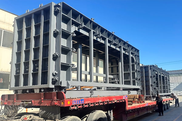
Box culvert mold: Inspect inside corner radius and wall junctions because they influence reinforcement clearance and concrete placement. For corner geometry and internal radius, the review should connect corner radius, cage clearance, and wall junction. The purpose is to establish what must be checked before the next production or purchasing decision, using the approved culvert section and joint drawing as the controlling reference.
When assessing a box culvert mold, use the approved culvert section and joint drawing for the project-specific limits and inspection method. The following checks connect corner radius with cage clearance and wall junction.

1. Corner radius: the first check
In a box culvert mold project, for corner geometry and internal radius, compare corner radius with cage clearance and wall junction under the same identified configuration. Inspect inside corner radius and wall junctions because they influence reinforcement clearance and concrete placement.
For buyers reviewing a box culvert mold, internal corner geometry should be checked with the intended reinforcement arrangement visible in the review. A radius that looks generous in an empty form may leave little clearance after the cage and spacers are installed. Resolve the placing and release requirements together, and record the approved corner detail with its mating panel revisions.
For a box culvert mold, wear parts deserve priority when they control geometry or closure. Track hinges, locating elements, joint inserts, and contact faces according to the actual design. Replacement parts need compatible revisions and restoration instructions. A spare part is valuable when it restores the verified arrangement, not merely when its external appearance resembles the old part.
2. Cage clearance: the connected interface
When assessing a box culvert mold, start a box culvert form review from the approved internal width, internal height, wall thickness, and segment length. Keep inside and outside dimensions distinct. The forming system must also accommodate the corner and joint geometry. A nominal rectangular size is too limited to define every interface needed for production and installation.
In projects involving a box culvert mold, diagonal checks are most useful when the base and measuring plane are defined. Equal diagonals taken at different heights do not establish the same geometry. Specify where the measurement is made and confirm the individual width and height references. Repeat the check after relocation or changes to the panel support arrangement.
3. Wall junction: the acceptance condition
For buyers reviewing a box culvert mold, concrete release conditions and mechanical clearance must be considered together. Record when a casting is released and inspect the locations of corner damage or drag marks. A trapped profile calls for a geometry or sequence review. Weak corners may also require a production-process review before any tooling change is justified.
For a box culvert mold, compaction access should match wall depth and reinforcement layout. Watch where voids occur on trial castings and relate the pattern to placing and access conditions. Repeated voids near one corner require a different investigation from random surface marks. Change one relevant variable at a time so the trial result remains interpretable.
4. Box culvert mold review options
When assessing a box culvert mold, the decision table connects corner geometry and internal radius with the evidence needed for corner radius, cage clearance, and wall junction.
| Decision point | Evidence to request | What it resolves |
|---|---|---|
| Corner radius | Defined reference and initial observations | Inspect inside corner radius and wall junctions because they influence reinforcement clearance and concrete placement. |
| Cage clearance | Installed configuration and connected interfaces | Whether the result changes with setup or handling |
| Wall junction | Representative trial and released-product inspection | Whether the agreed acceptance question has been answered |
| Return to routine production | Verified configuration, open actions, and recheck triggers | How the accepted result will be reproduced |

5. Production interfaces for box culvert mold
In projects involving a box culvert mold, after relocation, recheck the base and panel alignment. A form that worked in one bay may sit differently on new supports. Verify anchor locations, opening clearance, and inspection access before production resumes. Retain the original reference records so the team can compare the new installation with the approved arrangement.
For buyers reviewing a box culvert mold, when a joint runs around a rectangular segment, inspect transitions between straight and corner portions. A smooth straight length does not rule out a local step or interference at the corner. Use the approved joint drawing and retain a record of the complete perimeter, particularly after insert replacement or a configuration change.
6. A representative verification trial
In a box culvert mold project, for corner geometry and internal radius, record the incoming or assembled condition, the verified setup or intervention, and the final observation. Identify corner radius, cage clearance, and wall junction on the trial sheet. Keep failures and interruptions in the record. If an input, support, or measurement method changes, label the change so the next comparison remains interpretable.
When assessing a box culvert mold, corner regions combine changes in geometry with reinforcement congestion. Review bar positions, cover spacers, placement access, and compaction access together. A drawing that shows adequate cover may still leave little working room for the proposed casting process. Resolve the conflict before manufacturing a form that is difficult to use.
A multi-cell configuration should identify internal wall tools and the space needed to withdraw them. Compare each release movement with nearby reinforcement and embedded items. A sequence that works for the outer panels may not resolve the internal core. Require the difficult release interface to be demonstrated before the production plan assumes the full cycle.
7. Maintenance and repeatability of box culvert mold
An inner core needs a defined release path. Review the available inward movement, sequence of collapse where applicable, and clearance around reinforcement and openings. The sequence should allow the form to separate without pulling against concrete corners. Confirm the actual movement with the supplier rather than inferring it from a general product image.
For adjustable wall thickness, list which dimensions remain fixed and which shift. The effect may extend to outside size, reinforcement clearance, or a joint reference. Check those relationships on one coordinated drawing. Independent adjustment ranges are insufficient if the resulting combination no longer matches the finished component design.
8. Evidence to include in the technical inquiry
The inquiry for corner geometry and internal radius should include the approved culvert section and joint drawing, the planned material or product range, and observations of corner radius, cage clearance, and wall junction. Ask the supplier to identify its proposed configuration, excluded conditions, trial method, and supply boundary. A quotation is easier to compare when it answers these project-specific interfaces.
Explore Huier’s related product information and submit drawings through the technical inquiry page. Keep any proposed change to the requirement separate from a change to the equipment or tooling. Record which party must approve each change before it enters production.
9. Decision checklist for box culvert mold
Before releasing this project stage, confirm the approved revision, the evidence for corner radius, the connected check for cage clearance, and the acceptance observation for wall junction. Identify any product or condition that the trial did not cover. Keep the accepted configuration and the triggers for reinspection together with the order record.
Additional reading: precast concrete background. This reference is provided as technical background, without implying a product certification or an independent assessment of the proposed equipment.
For a box culvert mold project involving corner geometry and internal radius, send Shandong Huier Heavy Industry the approved drawing, representative input details, and observations for corner radius, cage clearance, and wall junction. Request a configuration review and a clearly defined quotation, trial, and inspection scope.
Frequently asked questions
What is the first priority in corner geometry and internal radius?
Inspect inside corner radius and wall junctions because they influence reinforcement clearance and concrete placement. Use the approved culvert section and joint drawing to define the acceptance question before changing the setup or ordering parts.
How should corner radius be recorded for box culvert mold?
Record the identified configuration and inspection reference. Compare corner radius with the agreed requirement and retain the connected observation for cage clearance.
Why does cage clearance matter when reviewing a box culvert mold?
It is one of the interfaces identified for corner geometry and internal radius. Check cage clearance against the project requirement, alongside the evidence for corner radius and wall junction, before assigning a cause.
What trial evidence is needed for box culvert mold?
Represent the actual input and configuration for corner geometry and internal radius. Retain results for corner radius, cage clearance, and wall junction, including failed checks.
What should a supplier proposal for box culvert mold contain?
It should address corner geometry and internal radius, the defined supply boundary, and the method for verifying corner radius. Include the approved culvert section and joint drawing in the inquiry.