Table of Contents
Introduction

A concrete pipe mould is one of the most important tooling systems in reinforced concrete pipe production. It determines the pipe diameter, wall thickness, length, end geometry, joint profile, and much of the visible surface condition of the finished product. Even when a pipe making machine, reinforcement cage, and concrete mix are correctly prepared, poor mould alignment or dimensional instability can still affect production consistency.
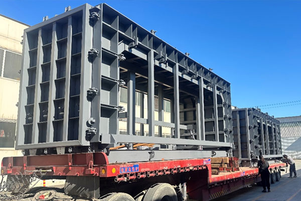
For precast plants, mould selection should therefore be considered together with the complete manufacturing process. The mould must match the intended pipe size, joint type, forming method, reinforcement arrangement, production frequency, and handling system. Huier’s plain end concrete pipe mould is designed for concrete pipe manufacturing and supports pipe diameters from 300 mm to 2400 mm, with listed lengths from 2000 mm to 4000 mm.
Understanding how concrete pipe moulds work, how different joint profiles change the design, and what should be checked during repeated production can help plants improve dimensional stability and reduce avoidable manufacturing variation.
What Is a Concrete Pipe Mould?
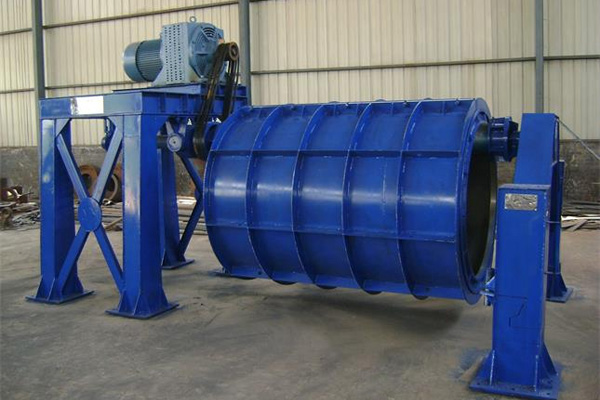
A concrete pipe mould is a forming system used to define the geometry of a precast concrete pipe during manufacturing. Depending on the production method, it can include an outer steel mould, internal forming components, end rings, joint-forming sections, support frames, locking mechanisms, and interfaces that connect the mould to the pipe making equipment.
The mould must maintain the required geometry while concrete is being placed and compacted. This is important because fresh concrete creates mechanical pressure against the mould surfaces, while vibration, rotation, or other forming actions can introduce additional forces.
In industrial production, the mould is expected to repeat the same geometry over many cycles. This makes rigidity, alignment, wear resistance, surface condition, and maintenance important parts of mould performance.
Why Mould Geometry Matters in Concrete Pipe Production
Concrete pipe is usually manufactured as a series of individual sections that later need to connect in the field. This means dimensional consistency is important not only within one pipe but also across an entire production batch.
The mould controls several critical dimensions:
- internal diameter
- external diameter
- wall thickness
- pipe length
- end squareness
- joint profile
- socket or spigot geometry
- surface shape
If the outer mould and internal forming section are not positioned concentrically, the pipe wall may become uneven. If an end-forming component moves during production, the joint may not match the intended geometry.
These errors can create difficulties during installation even when the concrete itself meets strength requirements. The American Concrete Pipe Association notes that concrete pipe joints are manufactured with specific geometries and tolerances, which is why joint configuration should be considered carefully during both production and installation.
Main Concrete Pipe Joint Types
Concrete pipe mould design changes significantly depending on the required end connection.
Extremo liso
A plain-end pipe has relatively simple end geometry compared with more complex joint systems. The pipe ends are generally flat, making this configuration useful for applications where the installation method does not require an integrated socket or tongue-and-groove connection.
Plain-end moulds can be comparatively straightforward, but dimensional control is still important. End faces should remain consistent so adjacent sections can be positioned correctly during installation.
Huier’s plain end mould is designed for municipal drainage, irrigation, and water conservancy applications and is intended to work with concrete pipe making equipment and related reinforcement systems.
Tongue-and-Groove Joint
Tongue-and-groove pipe ends contain complementary profiles that help adjacent pipe sections locate relative to one another.
The mould must reproduce both joint surfaces accurately. Changes in the profile can affect how well sections fit together, so the forming rings and end components need stable positioning during each casting cycle.
Compared with plain-end designs, the mould geometry becomes more complex because the end profile contributes directly to field assembly.
Socket-and-Spigot Joint
Socket-and-spigot designs use an enlarged socket at one end and a corresponding spigot at the other.
These joints require more detailed mould geometry because both ends must match the intended dimensional relationship. In applications involving sealing systems, the joint profile can become particularly important.
Manufacturing consistency matters because the connection between consecutive pipe sections depends on repeatable socket and spigot dimensions.
Outer Mould and Inner Forming Geometry
A concrete pipe mould generally depends on the relationship between its outer and inner forming surfaces.
The outer mould defines the external geometry, while the internal forming section determines the internal diameter. The spacing between these surfaces establishes pipe wall thickness.
Concentricity is therefore one of the most important dimensional controls.
If the internal and external forming surfaces are offset, one side of the pipe wall may become thicker while the opposite side becomes thinner. This can create both dimensional and reinforcement-cover inconsistencies.
For this reason, the mould should include reliable reference points that allow operators to verify positioning before the forming cycle begins.
How the Mould Works With the Reinforcement Cage
Many concrete drainage pipes include a welded reinforcement cage positioned between the inner and outer forming surfaces.
The cage must remain correctly located during mould assembly and forming. If it shifts too close to one side, the concrete cover around the reinforcement may become inconsistent.
Huier’s reinforcement cage rolling welder is designed for reinforced concrete drainage pipe production and can support cages for plain, tongue-and-groove, and socket joint configurations.
The cage, mould, and pipe machine should therefore be planned as a connected system. Cage diameter, longitudinal reinforcement, spiral spacing, concrete wall thickness, and mould dimensions all influence one another.
Concrete Pipe Moulds and Different Production Methods
Concrete pipe can be manufactured using several forming methods, and the mould needs to suit the selected process.
The American Concrete Pipe Association describes multiple production methods in which mechanical action is used to place and compact concrete inside the form. Dry-cast systems generally use low-slump concrete and mechanical compaction, while wet-cast production keeps the concrete inside the inner and outer forms until sufficient initial strength develops.
This distinction matters because mould operating conditions can vary considerably.
A dry-cast mould may experience repeated rapid production cycles, while a wet-cast mould may remain occupied for longer before demoulding.
The expected process should therefore influence mould structure, opening design, handling, maintenance, and production planning.
Mould Rigidity and Structural Stability
A mould must maintain its geometry while it is exposed to concrete pressure and forming forces.
Steel is commonly used in industrial concrete pipe mould construction because a properly designed steel structure can provide the stiffness and durability needed for repeated manufacturing.
The structural frame may include stiffening ribs, flanges, support rings, reinforcing sections, and locking mechanisms.
These features help distribute loads and reduce local deformation.
However, adding steel indiscriminately does not automatically improve mould performance. Excessive weight can make handling more difficult and increase the load placed on cranes, transfer equipment, and operators.
The design should therefore balance rigidity with practical operation.
Why Alignment Is Critical
Reusable moulds are repeatedly opened, cleaned, repositioned, and closed.
Every production cycle creates another opportunity for alignment variation.
Mechanical locating points, flanges, guide pins, fasteners, and locking systems help the mould return to the intended position.
Operators should pay particular attention to:
- circumferential joint alignment
- mould seam closure
- end ring position
- centerline alignment
- locking points
- internal forming section position
A mould can appear visually normal while still showing small dimensional changes at important reference surfaces. Periodic measurement is therefore useful for high-volume production.
How Mould Condition Affects Surface Quality
The finished concrete surface reflects many characteristics of the mould surface.
Hardened concrete residue, corrosion, scratches, deformation, damaged welds, and contaminated interfaces can affect the surface of subsequent pipe sections.
Cleaning therefore has two purposes.
First, it helps preserve the visible surface of the pipe.
Second, it prevents accumulated material from interfering with mould closure and alignment.
A small amount of hardened concrete between two mating mould sections can prevent them from closing completely, creating dimensional variation that becomes more noticeable over repeated cycles.
Routine cleaning should therefore focus especially on seams, flanges, contact faces, joint-forming sections, and locking areas.
How Moulds Affect Pipe Joint Consistency
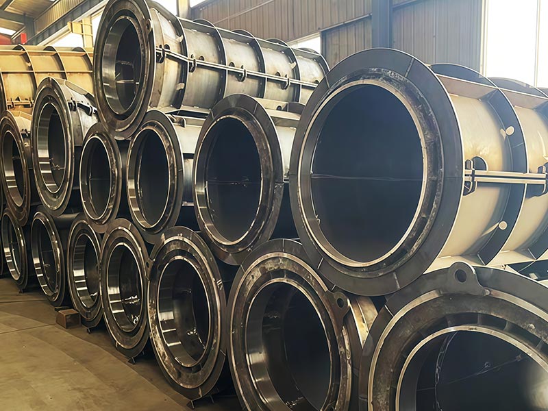
Joint geometry deserves particular attention because individual pipe sections need to connect during installation.
The ACPA notes that pipe and culvert manufacturing requirements are commonly governed by ASTM or equivalent AASHTO standards, with quality control extending to finished products and manufacturing documentation.
For mould production, this means joint-forming components should maintain repeatable dimensions across production cycles.
Wear at an end ring, locating surface, or joint-forming insert can gradually affect the finished profile even if the main cylindrical section remains unchanged.
Joint components should therefore be treated as precision working parts rather than secondary mould accessories.
Important Factors When Selecting a Concrete Pipe Mould
A concrete pipe mould should be selected according to the actual production program.
| Factor | Why It Matters |
|---|---|
| Pipe diameter | Defines the core mould size |
| Pipe length | Determines mould length and handling requirements |
| Wall thickness | Influences inner and outer geometry |
| Joint type | Determines end-forming design |
| Production method | Affects mould operating conditions |
| Reinforcement cage | Requires dimensional compatibility |
| Production frequency | Influences durability requirements |
| Handling system | Affects lifting and mould movement |
| Surface requirements | Influence mould finish and maintenance |
| Pipe machine | Determines mechanical compatibility |
Considering these factors together reduces the risk of selecting a mould that fits the nominal pipe dimensions but does not integrate effectively with the actual production line.
Mould Changeover and Multi-Size Production
Many precast plants produce more than one pipe diameter.
This means mould changeover becomes part of daily production planning.
A practical system should allow moulds to be identified, moved, prepared, installed, aligned, and removed without unnecessary delay.
Changeover time depends on the equipment layout, mould weight, lifting system, fastening method, and machine interface.
Plants producing many specifications may benefit from standardized handling and setup procedures so operators can repeat the same sequence for every mould change.
Clear identification is also important. Diameter, length, joint profile, and compatible machine configuration should be easy to verify before installation.
Handling Large Concrete Pipe Moulds
As pipe diameter and length increase, mould weight and overall dimensions also become more significant.
Huier’s current plain-end product range lists mould diameters extending up to 2400 mm and lengths up to 4000 mm, illustrating why material handling should be considered during production-line planning.
Large moulds may require cranes, lifting beams, dedicated lifting points, or transfer equipment.
The workshop should provide enough space for safe movement without forcing the mould through narrow or obstructed paths.
Mould lifting points should also be positioned so that the structure remains stable during handling. Incorrect lifting can introduce unnecessary stress or distortion into large mould sections.
Common Concrete Pipe Mould Problems
Several recurring problems can affect production quality.
Uneven Wall Thickness
This may result from poor concentricity between internal and external forming surfaces, reinforcement displacement, or incorrect machine alignment.
Joint Profile Variation
Wear, loose end-forming components, or incorrect positioning can change socket, spigot, or tongue-and-groove dimensions.
Visible Mould Seam Marks
Poor closure, surface contamination, or damaged seam interfaces can create more pronounced marks on the finished pipe.
Difficulty Demoulding
Concrete residue, damaged surfaces, incorrect release preparation, deformation, or inappropriate demoulding timing can increase resistance during removal.
Repeated Dimensional Drift
Gradual wear or loosening at reference points can cause dimensions to change over many production cycles.
These problems should be investigated systematically instead of assuming every defect originates from the concrete mix or forming machine.
Maintenance for Repeated Production
Concrete pipe mould maintenance should include daily operational checks as well as periodic dimensional inspection.
Frequently inspected areas may include:
- mould surfaces
- seams and flanges
- locking devices
- locating points
- structural ribs
- end-forming sections
- lifting points
- fasteners
- welds
- alignment references
Damaged or worn components should be addressed before they begin affecting an entire production batch.
The American Concrete Pipe Association’s QCast program emphasizes inspection of materials, finished products, handling and storage procedures, testing, and quality-control documentation as part of concrete pipe plant quality assurance.
Integrating the Mould With a Concrete Pipe Production Line
A concrete pipe mould does not operate independently.
A typical production workflow may include:
Reinforcement cage preparation → Mould setup → Cage positioning → Concrete feeding → Pipe forming and compaction → Demoulding → Curing → Inspection
Each stage should be compatible with the mould dimensions and operating sequence.
For example, the reinforcement cage should be ready before the mould is required for forming. The lifting equipment should be available when the mould needs to be moved. Finished pipes should have a defined transfer path toward curing and inspection.
Huier’s current applications page positions concrete pipe forming, mould systems, reinforcement equipment, and production-line planning as connected parts of a broader precast solution.
This system-level approach becomes increasingly important as production volume increases.
How to Evaluate a Concrete Pipe Mould Before Production

Before regular production begins, the mould should be checked both dimensionally and operationally.
The production team should confirm that:
- the mould closes completely
- critical dimensions match the required pipe specification
- end-forming sections are correctly positioned
- reinforcement can be installed without interference
- the mould fits the pipe making equipment
- lifting points and handling methods are practical
- opening and demoulding can be performed safely
- all locking devices operate consistently
A trial production cycle can reveal issues that are difficult to identify during a static inspection.
The first finished pipe can then be measured for diameter, length, wall thickness, joint geometry, and visible surface condition before larger batch production begins.
Conclusion
A concrete pipe mould is a precision production system that directly affects pipe diameter, wall thickness, length, joint geometry, surface condition, and repeatability.
Different pipe types require different mould configurations. Plain-end, tongue-and-groove, and socket-and-spigot pipes each introduce specific requirements for end-forming components and dimensional control.
Reliable production depends on mould rigidity, concentricity, alignment, reinforcement compatibility, machine integration, cleaning, handling, and maintenance. These factors should be evaluated together rather than treating the mould as a simple steel container.
When the concrete pipe mould is properly matched with the pipe making machine, reinforcement cage system, production method, and workshop workflow, it can support stable repeated manufacturing and more predictable finished-pipe geometry.
FAQ
What is a concrete pipe mould used for?
A concrete pipe mould defines the geometry of a precast concrete pipe during manufacturing. It helps control pipe diameter, wall thickness, length, surface shape, and end-joint profile while concrete is formed and compacted.
What types of concrete pipe moulds are available?
Common configurations include plain-end, tongue-and-groove, and socket-and-spigot mould systems. The appropriate type depends on the pipe design, installation method, required joint performance, and compatible production equipment.
Why is concentricity important in a concrete pipe mould?
Concentricity maintains the correct relationship between the inner and outer forming surfaces. Poor concentricity can produce uneven wall thickness and inconsistent reinforcement cover around the pipe circumference.
Can one concrete pipe mould produce different pipe sizes?
A single fixed mould generally corresponds to a defined diameter and geometry, although some components or production systems may allow adjustable or interchangeable sections. Plants producing many pipe sizes typically use multiple compatible mould configurations.
What should be checked during concrete pipe mould maintenance?
Operators should inspect mould surfaces, seams, flanges, locating points, locking systems, joint-forming sections, structural frames, lifting points, fasteners, and dimensional references. Cleaning and periodic dimensional verification are particularly important in repeated production.