Table of Contents
Introduction

Lifting equipment has a direct influence on how safely and efficiently materials move through a workshop, production line, storage area, assembly zone, or outdoor handling site.
The correct system does more than raise a heavy object. It must pick up the load from the right position, move it through a defined path, maintain control during travel, place it accurately, and return for the next cycle without disrupting surrounding operations.
A crane with sufficient rated capacity can still be unsuitable if it cannot reach the required pickup point. A fast hoist can reduce cycle time but make precise assembly more difficult. A structurally strong system can still create operational problems when hook approach, control visibility, maintenance access, or rigging requirements are overlooked.
For that reason, selecting lifting equipment should begin with the complete material-handling task. Load weight is important, but it is only one part of the decision. Load shape, center of gravity, travel path, operating frequency, environmental conditions, supporting structure, required positioning accuracy, and inspection procedures must also be evaluated.
This guide explains how these factors work together and how a well-matched lifting system can improve material flow without adding unnecessary complexity.
What Lifting Equipment Actually Includes
Lifting equipment is a broad term covering machines and systems used to raise, lower, suspend, position, or transfer loads.
In industrial settings, the category commonly includes overhead cranes, gantry cranes, electric hoists, single-girder systems, double-girder systems, specialized process cranes, lifting trolleys, hooks, and related control equipment.
The industrial lifting equipment range includes electric hoist gantry cranes, single-girder overhead cranes, general-purpose gantry cranes, general-purpose overhead cranes, metallurgical overhead cranes, and newer electric hoist crane configurations. These systems address different combinations of load capacity, working area, operating environment, and duty requirements.
Lifting, Lowering, and Horizontal Movement
A hoist primarily raises and lowers a load. A complete crane system adds one or more directions of horizontal movement.
An overhead crane may provide three main motions:
- The hoist raises and lowers the load.
- The trolley moves across the bridge.
- The bridge travels along the runway.
Together, these motions create a rectangular working area. The useful performance of the system depends on how completely the hook can access that area.
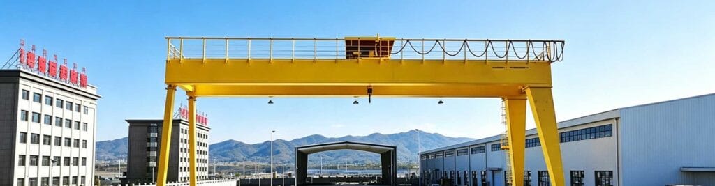
A gantry crane works on a similar principle, but its bridge is supported by legs that travel on ground-level rails or wheels rather than relying entirely on an elevated building runway.
The Difference Between a Hoist and a Complete Crane System
A hoist is only one component of many lifting systems. Its rated capacity and lifting speed do not fully describe the crane’s operational ability.
The complete system may also include:
- Bridge girders
- End carriages
- Trolley frames
- Travel drives
- Rails and runway structures
- Electrical supply systems
- Control panels
- Braking systems
- Limit switches
- Hooks and lifting accessories
These components must be designed to work together. Installing a suitable hoist on an unsuitable bridge or runway does not create a reliable lifting solution.
Standard and Application-Specific Equipment
General-purpose lifting equipment is suitable when loads and operating conditions remain within common industrial requirements. Application-specific systems are needed when the load, environment, or process introduces unusual demands.
Examples include handling high-temperature materials, long flexible components, large precast elements, sensitive machinery, rotating loads, or equipment requiring synchronized lifting points.
Customization should solve a defined operational problem. Adding complexity without a clear purpose may increase maintenance requirements and reduce system availability.
Start With the Load, Not the Machine
A reliable selection process begins by documenting the load.
The common mistake is to start with a preferred crane type and then try to adapt the handling task around it. A better method is to define the load and movement first, then determine which equipment structure supports them most effectively.
Maximum and Routine Load Weight
The heaviest planned load establishes an important capacity requirement, but the routine load is equally relevant.
A crane that occasionally handles a heavy component but spends most of its time moving lighter loads may require a different speed and control strategy from a crane that operates near its rated capacity during every cycle.
Record both values:
- Maximum expected lifted load
- Typical operating load
- Weight of lifting accessories
- Possible future load increase
- Variation between different product models
The weight of slings, lifting beams, clamps, spreaders, magnets, or other below-the-hook devices must be included. The crane supports the total suspended weight, not only the product itself.
Load Dimensions and Center of Gravity
Two loads with the same weight can behave very differently.
A compact machine component may remain stable below a single hook. A long beam, concrete panel, steel structure, or assembled module may require a spreader beam or multiple lifting points to prevent bending and rotation.
The center of gravity determines how the load hangs. When the hook is not positioned above it, the load may tilt as soon as it leaves the support surface.
Before selecting lifting equipment, document:
- Overall load length, width, and height
- Center-of-gravity location
- Available lifting points
- Permitted sling angles
- Areas that must not be compressed
- Orientation during pickup and placement
For products with variable internal components, the center of gravity may shift from one unit to another. The lifting method must account for this variation.
Fragile, Flexible, Hot, or Irregular Loads
Load condition can be more important than load weight.
A fragile component may require smooth acceleration. A flexible product may need distributed support. A hot load may affect hooks, ropes, electrical components, and operator positioning. An irregular load may rotate or swing unpredictably.
The lifting system should be specified around the most demanding normal load condition rather than an idealized, centrally balanced object.
Below-the-Hook Lifting Devices
Hooks rarely connect directly to the product. Slings, grabs, lifting beams, clamps, and other attachments transfer the force between the crane and the load.
These devices affect:
- Total suspended weight
- Required lifting height
- Headroom
- Load balance
- Hook rotation
- Sling angle
- Pickup time
- Placement accuracy
A lifting beam may improve load stability but reduce available lifting height. A clamp may speed up handling but require a carefully controlled surface condition. The attachment and crane should therefore be evaluated as one system.
Match the Equipment Type to the Required Movement
Different equipment structures create different working areas. The best option is the one that matches the load path with the least unnecessary movement.
Overhead Cranes
An overhead crane travels on elevated runways and keeps most of the floor area open.
It is well suited to workshops, production buildings, assembly areas, storage zones, and process lines where materials need to move repeatedly across a defined rectangular area.
Typical advantages include:
- Broad floor coverage
- Minimal interference with ground traffic
- Direct movement between production stations
- Flexible hook positioning
- Integration with building layouts
- Suitability for repeated handling cycles
The supporting building or independent runway must be capable of carrying crane loads. Existing structures should not be assumed suitable without technical verification.
Gantry Cranes
A gantry crane supports its bridge on legs. This configuration can be useful when an elevated runway is not available or when lifting must take place in an open area.
Common applications include outdoor yards, storage areas, prefabrication sites, equipment assembly zones, and temporary or independent work areas.
A gantry crane requires careful attention to:
- Rail or travel surface alignment
- Leg clearance
- Wind exposure
- Ground-level traffic
- Cable routing
- Anti-skid and anchoring measures
- End-of-travel protection
Its legs occupy floor or yard space, so the travel route must remain free from materials, vehicles, and temporary obstacles.
Electric Hoist Systems
Electric hoist cranes can provide a practical balance of compact structure, controlled lifting, and straightforward operation.
They are often appropriate for moderate-capacity material handling, equipment maintenance, component assembly, loading operations, and routine workshop movement.
The hoist should not be selected only by rated capacity. Rope reeving, lifting speed, motor duty, brake design, hook travel, control method, and maintenance access also affect performance.
Specialized Lifting Equipment
Specialized lifting equipment is required when the load or process exceeds general-purpose conditions.
Such systems may include additional braking, heat protection, redundant components, synchronized hoists, rotating devices, custom grabs, enhanced monitoring, or application-specific control logic.
Specialization should be based on a documented risk or process requirement. Every added function should have a clear operational purpose and a defined inspection method.
Define the Working Area and Hook Coverage
The nominal span of a crane does not tell you exactly where the hook can reach.
End carriages, trolley dimensions, buffers, control panels, building columns, wall clearances, and safety distances reduce the usable working area. This difference becomes important when loads must be picked up close to a wall, machine, storage rack, or runway end.
Span and Runway Length
Span is the distance across the crane bridge. Runway length determines longitudinal travel.
These dimensions should be based on actual pickup and placement coordinates rather than general building dimensions.
A useful layout drawing should show:
- Load pickup zones
- Final placement zones
- Storage areas
- Machinery
- Columns and walls
- Pedestrian routes
- Vehicle routes
- Restricted areas
- Future equipment positions
The aim is to ensure that the hook can complete the real handling task, not merely travel across an empty floor plan.
Lifting Height
Lifting height is the vertical distance through which the hook can move, but usable clearance depends on the entire lifting arrangement.
Consider:
- Maximum hook height
- Lowest required pickup level
- Height of the load
- Height of lifting accessories
- Required clearance above obstacles
- Deflection under load
- Installation and maintenance space
For tall equipment or deep production pits, the standard hook travel may not be sufficient even when the building has adequate overall height.
Hook Approach
Hook approach describes how close the hook can move to the side or end of the working area.
Poor hook approach can force operators to drag, push, or transfer loads after lifting. This reduces the benefit of the crane and can introduce uncontrolled handling.
When a critical pickup point is close to a wall or column, the trolley and bridge geometry should be reviewed before the equipment arrangement is finalized.
Restricted Areas and Obstacles
Some areas should not be crossed by suspended loads. These may include occupied workstations, control rooms, process equipment, storage of sensitive materials, and regular pedestrian paths.
The lifting route should avoid these areas whenever the layout permits. Where avoidance is not possible, administrative controls alone may be insufficient; physical barriers, restricted access, travel limits, or alternative handling routes may be required.
Evaluate Capacity Without Relying on Load Weight Alone
Rated capacity is essential, but a safe selection cannot be based on a single weight figure.
Rated Capacity
The equipment must be rated for the total suspended load, including the product and all lifting attachments.
The rating should be clearly identified and consistent across the hoist, hook, ropes, trolley, bridge, end carriages, runway, rigging, and support structure.
Using an oversized hoist does not automatically increase the capacity of the complete crane. The lowest-rated critical component limits the system.
Dynamic Effects
A suspended load creates additional forces when it accelerates, stops, swings, or is lifted suddenly.
Rapid starts and abrupt braking can increase stress on structural and mechanical components. Pulling a load sideways can introduce forces that the hoist was not designed to resist.
Smooth motion control is therefore not only a productivity feature. It also helps reduce load swing, impact, and repeated mechanical stress.
Uneven Load Distribution
Multi-point lifting requires more than dividing the total weight by the number of hooks.
Small differences in rope length, attachment position, structural stiffness, or hoist movement can cause one point to carry a larger share of the load.
Synchronized systems should include an appropriate method of load balancing or monitoring when uneven distribution could affect safety or product integrity.
Rigging and Lifting Accessories
Rigging condition directly affects the complete lifting operation. One official reference on rigging equipment inspection requirements states that rigging should be inspected before use during each shift and that defective equipment should be removed from service. The same reference requires legible identification showing the recommended safe working load.
Applicable local regulations and technical standards should always be confirmed for the installation. Inspection practices should cover both the crane and the equipment connecting the crane to the load.
Consider Duty Cycle and Operating Frequency
Two cranes with the same capacity can require very different designs when their operating frequency differs.
A crane used for occasional maintenance may remain idle for long periods. A production crane may perform repeated lifting, trolley travel, and bridge travel throughout every shift.
Occasional Maintenance Lifting
Maintenance equipment often needs broad coverage and reliable low-speed positioning but may not require high travel speeds.
Because it operates infrequently, inspection before use becomes especially important. Long idle periods can allow corrosion, brake sticking, lubricant deterioration, or control faults to develop without being noticed.
Regular Production Handling
A production crane should match the rhythm of the surrounding process.
The required cycle includes more than lifting time. It may involve:
- Moving to the pickup position
- Connecting the load
- Taking up sling tension
- Raising the load
- Traveling horizontally
- Lowering and positioning
- Releasing the attachment
- Returning for the next load
Improving only the lifting speed may have little effect if attachment or positioning consumes most of the cycle.
High-Frequency Industrial Operation
High-frequency use increases demand on motors, brakes, wheels, bearings, wire ropes, electrical contactors, and travel mechanisms.
The equipment should be selected according to expected operating time, load spectrum, number of starts, travel distance, and proportion of lifts near rated capacity.
An average load figure alone can hide demanding operating patterns. Frequent short movements may create more motor starts and brake cycles than fewer long movements.
Starts, Stops, and Travel Distance
A process with short repetitive movements requires different control behavior from one involving long-distance transport.
Repeated starts increase thermal and mechanical demands. Long travel distances make acceleration, stable travel, and controlled deceleration more important.
The equipment specification should describe actual movement patterns rather than simply stating that the crane will operate “frequently.”
Balance Speed, Precision, and Load Control
Higher speed can reduce travel time, but it can also increase swing and make positioning more difficult.
The correct speed strategy depends on the task.
Lifting Speed
Fast lifting is useful when the load travels through a large vertical distance and does not require delicate positioning.
Low lifting speed is more valuable during:
- Machine assembly
- Mold positioning
- Equipment installation
- Alignment with bolts or locating pins
- Placement of fragile components
- Removal of fitted parts
A two-speed or variable-speed system can provide faster movement during open travel and controlled movement near the final position.
Variable-Frequency Control
Variable-frequency drives can support smoother acceleration and deceleration. This reduces sudden movement and helps operators control suspended loads.
The benefit is greatest when the control settings match the load and process. Excessively slow acceleration may reduce productivity, while overly aggressive settings can still produce swing.
Low-Speed Positioning
Precision positioning depends on more than minimum speed. Brake response, mechanical clearances, rope behavior, trolley wheel condition, and operator visibility also affect control.
When a load must align with equipment, the final approach direction should be considered. A clear line of sight and predictable control response can be more valuable than high maximum speed.
Sway Management
Load sway develops when the hook and load lag behind crane movement.
It can be reduced through:
- Smooth acceleration
- Controlled deceleration
- Appropriate travel speed
- Shorter suspension length where practical
- Correct load balance
- Trained operation
- Automated anti-sway functions where justified
Good material flow does not mean moving every load as fast as possible. It means moving at the fastest speed that remains stable and repeatable.
Review the Supporting Structure and Operating Environment
Lifting equipment transfers forces into runways, foundations, rails, columns, or supporting frames. These structures are part of the lifting system.
Building-Supported Overhead Cranes
An overhead crane places vertical and horizontal forces on its runway.
The structure should be checked for:
- Maximum wheel loads
- Horizontal travel forces
- Rail alignment
- Beam deflection
- Column capacity
- Connection strength
- Fatigue effects
- Building movement
A building may appear large and strong but still lack suitable runway geometry or load capacity.
Independent Gantry Crane Structures
Gantry cranes transfer loads through their legs into rails, wheels, or the ground surface.
The travel path must remain level and aligned. Settlement or rail variation can increase wheel wear, skewing, structural stress, and drive resistance.
Outdoor installations also require consideration of wind, drainage, temperature variation, and securing methods when the crane is parked.
Indoor and Outdoor Conditions
Indoor equipment is generally better protected from weather, but it may operate around dust, moisture, fumes, heat, or restricted ventilation.
Outdoor equipment requires suitable protection for motors, electrical enclosures, brakes, rails, control devices, and structural surfaces. Water should not collect in girders, platforms, or electrical areas.
Heat, Dust, Moisture, and Corrosion
Environmental conditions influence material selection and maintenance frequency.
Dust can affect brakes, electrical components, and moving mechanisms. Moisture can damage electrical insulation and accelerate corrosion. Heat can affect motors, cables, lubricants, controls, and operator comfort.
Protective measures should address the actual source of exposure rather than relying only on a general coating specification.
Build Safety Into the Complete Lifting System
Safety features work best when they are integrated into the equipment design and operating layout.
Overload Protection
Overload protection helps prevent lifting beyond defined equipment limits. It should not be used as a substitute for knowing the load weight.
Unexpected overload activation may indicate an incorrect load estimate, snagged load, unsuitable rigging, or process problem. The cause should be identified before the operation continues.
Travel Limits
Upper and lower hoist limits help prevent movement beyond the intended hook range. Bridge and trolley travel limits define boundaries within the working area.
Limit switches are protective devices, not routine stopping controls. Normal operation should stop the equipment before a final safety limit is reached.
Emergency Stopping
Emergency stopping should interrupt hazardous movement in a predictable manner. Control locations must remain accessible to the operator.
After an emergency stop, the system should not automatically restart when the control is reset. The cause of the stop should be checked before operation resumes.
Brakes and Anti-Collision Controls
Brakes must hold and control loads under the intended operating conditions. Travel brakes should support stable stopping without excessive wheel slip or load swing.
When multiple cranes share a runway, anti-collision or spacing systems may be required to prevent unsafe approach.
Inspection and Operator Visibility
The operator should be able to see the load path or receive reliable guidance from a designated signal person.
Blind spots, columns, machinery, stacked materials, and long loads can reduce visibility. The control method and operator position should reflect these conditions.
Select the Right Control Method
Control selection affects visibility, movement, operator location, and communication.
Pendant Control
A pendant allows the operator to walk near the load. It can provide good visibility during short, controlled movements.
The operator must remain clear of the suspended load and avoid becoming trapped between the load and surrounding structures. The pendant cable should not create a snagging hazard.
Wireless Remote Control
Wireless control allows the operator to select a safer viewing position and move away from the crane’s fixed path.
A clear operating procedure should prevent unauthorized use or confusion when more than one remote-controlled crane operates in the same area.
Operator Cabin
A cabin may be appropriate for high-duty systems, long travel distances, elevated work areas, complex operations, or environments where the operator requires a protected position.
Visibility, communication, access, emergency escape, environmental control, and ergonomic layout should be considered together.
Semi-Automated Operation
Semi-automated systems can support repeatable positioning, predefined travel zones, controlled speeds, or process coordination.
Automation should not be added only because it is technically possible. It is most effective when load positions are predictable, operating cycles are repetitive, and sensors can reliably confirm safe conditions.
Comparing Common Types of Lifting Equipment
| Equipment type | Typical working pattern | Main advantages | Key considerations |
|---|---|---|---|
| Single-girder overhead crane | Repeated lifting across a workshop or production bay | Compact structure, broad floor coverage and practical routine handling | Capacity, headroom, runway strength and hook approach |
| Double-girder overhead crane | Heavier loads or larger spans with demanding duty | Higher structural capacity, improved hook height options and equipment access | Building support, maintenance platforms and total system weight |
| Electric hoist overhead crane | General workshop, maintenance and assembly handling | Controlled lifting, relatively compact design and flexible operation | Hoist duty, lifting speed, rope arrangement and brake performance |
| General-purpose gantry crane | Outdoor yards or areas without elevated runways | Independent support structure and wide application range | Ground condition, rail alignment, leg clearance and wind protection |
| Electric hoist gantry crane | Moderate material handling in open or semi-open areas | Practical hoisting with an independent travelling structure | Travel path, electrical supply and outdoor protection |
| Specialized process crane | High-duty, high-temperature or process-integrated work | Application-specific safety, control and handling functions | Detailed operating conditions, redundancy and maintenance planning |
| Customized lifting system | Irregular loads or unique movement requirements | Geometry, controls and attachments matched to the process | Clear technical data, interface control and verification testing |
Plan Inspection and Maintenance From the Beginning
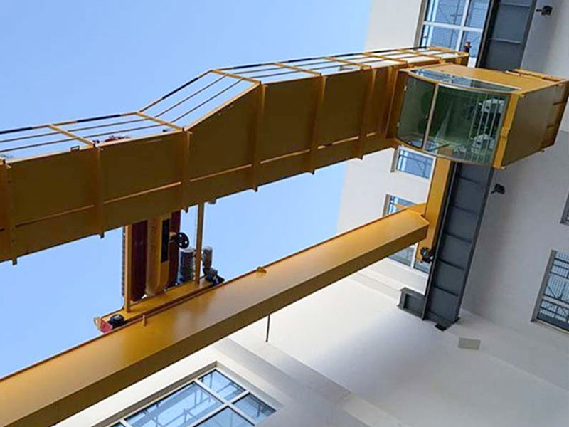
Maintenance access should be considered before the crane arrangement is approved.
A component that cannot be reached safely is less likely to receive consistent inspection. Temporary access methods can also increase downtime and expose maintenance personnel to unnecessary risk.
Accessible Maintenance Points
Provide practical access to:
- Hoist machinery
- Brakes
- Rope drums
- Electrical panels
- Trolley drives
- Bridge drives
- Limit switches
- Rail connections
- Lubrication points
- Wheels and bearings
Access platforms, walkways, ladders, isolation points, and fall-protection provisions should be coordinated with the equipment and building layout.
Wire Ropes, Hooks, and Brakes
Wire ropes should be checked for wear, broken wires, crushing, corrosion, and correct spooling. Hooks require inspection for deformation, cracking, wear, and latch condition.
Brakes should hold the load reliably and release consistently. Changes in stopping distance, noise, heat, or load drift should be investigated promptly.
Runways, Wheels, and Rails
Rail alignment affects travel resistance, wheel wear, structural loading, and crane skewing.
Repeated flange contact, unusual noise, vibration, or uneven wheel wear may indicate alignment, level, drive, or structural problems. Replacing worn wheels without correcting the underlying cause can lead to repeated failure.
Electrical and Control Components
Control equipment should be kept clean, secure, and protected from moisture and heat.
Loose terminals, damaged cables, worn contactors, faulty limits, and unreliable controls can create intermittent problems that are difficult to diagnose. Maintenance records help identify repeated faults and plan corrective work.
Common Lifting Equipment Selection Mistakes
Selecting Only by Rated Capacity
Capacity does not describe hook coverage, lifting height, control accuracy, duty cycle, or environmental suitability.
A complete specification must explain what the crane will do and how often it will do it.
Ignoring the Weight of Lifting Accessories
A lifting beam, clamp, or spreader may represent a significant part of the suspended load. It can also reduce available lifting height.
Accessories should be included in load and clearance calculations from the beginning.
Using Building Dimensions as the Working Area
Walls, end carriages, trolley dimensions, buffers, and structural clearances reduce actual hook coverage.
Pickup and placement coordinates should be checked against the real hook path.
Prioritizing Speed Over Control
Higher speed can create more swing and increase positioning time. A well-selected variable-speed system may complete the overall cycle more efficiently than a faster system with poor low-speed control.
Underestimating Duty Cycle
A crane used repeatedly near its rated capacity requires a different mechanical and electrical design from equipment used occasionally for maintenance.
Operating frequency and load spectrum should be documented rather than described with vague terms.
Forgetting the Supporting Structure
The crane, runway, columns, rails, and foundations form one load path. Equipment selection should not be completed before structural suitability is confirmed.
Treating Rigging as a Separate Issue
The crane cannot compensate for an unsuitable sling arrangement, unstable center of gravity, damaged attachment, or poorly positioned lifting point.
The load, rigging, and crane must be reviewed together.
Leaving Maintenance Access Until Installation
Adding walkways, platforms, or service clearance after equipment installation is usually more difficult. Maintenance access should be part of the original layout.
A Practical Equipment Selection Process
Step 1: Create a Load Register
List every normal and occasional load, including dimensions, weight, center of gravity, lifting points, attachments, and required orientation.
Do not design only around the heaviest load. Identify which load is longest, most fragile, most difficult to balance, and most frequently handled.
Step 2: Map Every Movement
Mark pickup points, travel routes, placement positions, obstacles, restricted zones, and surrounding traffic.
Use actual coordinates and elevations. This reveals the required span, runway length, lifting height, and hook approach.
Step 3: Define the Operating Cycle
Record lifting distance, trolley travel, bridge travel, number of cycles, operating hours, starts per cycle, and proportion of loads near rated capacity.
This information supports the selection of motors, brakes, controls, ropes, wheels, and structural duty.
Step 4: Review the Installation Environment
Document whether the equipment will operate indoors or outdoors and whether it will encounter dust, moisture, heat, corrosive exposure, wind, or restricted ventilation.
Confirm the suitability of the supporting building, runway, rails, foundations, and electrical supply.
Step 5: Choose the Handling Method
Define the hook, sling, lifting beam, clamp, grab, or other attachment. Confirm headroom, load stability, attachment time, and inspection requirements.
Step 6: Establish Control and Safety Functions
Choose the operating method according to visibility and process needs. Define overload protection, limits, brakes, emergency stopping, anti-collision requirements, warning devices, and restricted travel zones.
Step 7: Plan Inspection and Maintenance
Provide access to critical components and establish inspection intervals according to equipment use, environmental exposure, manufacturer instructions, and applicable requirements.
A maintenance plan should exist before the equipment begins production duty.
Conclusion
The most effective lifting equipment is not simply the system with the highest capacity or fastest lifting speed. It is the system that matches the load, movement path, operating frequency, installation environment, control requirements, and maintenance capability.
A reliable selection process should answer several practical questions:
- What is being lifted?
- Where is its center of gravity?
- Which lifting accessories are required?
- Where must the hook reach?
- How often will the equipment operate?
- How accurately must the load be positioned?
- What supports the crane?
- What environmental conditions will it face?
- How will operators inspect and maintain it?
Overhead cranes can provide broad coverage while preserving floor space. Gantry cranes offer an independent solution for open areas or facilities without elevated runways. Electric hoist systems support routine workshop handling, while specialized cranes address demanding process and environmental conditions.
The final system should be designed as one coordinated load path extending from the supporting structure to the crane, hoist, hook, rigging, lifting point, and load itself. When those elements are evaluated together, lifting equipment becomes more than a machine—it becomes a stable part of the production flow.
Load data, working-area drawings, operating frequency, lifting height, environmental conditions, and control requirements can be submitted for a project-specific lifting solution that aligns the crane structure and operating functions with the actual handling process.
FAQ
What equipment is used for lifting heavy industrial loads?
Overhead cranes, gantry cranes, electric hoists, and specialized process cranes are commonly used. The appropriate option depends on load weight, dimensions, center of gravity, movement path, lifting height, operating frequency, environment, and supporting structure.
How is lifting equipment capacity selected?
Capacity should include the load, slings, lifting beams, clamps, and all other suspended accessories. Selection must also consider dynamic forces, uneven multi-point loading, duty cycle, lifting frequency, structure capacity, and possible future operating requirements.
What is the difference between an overhead crane and a gantry crane?
An overhead crane travels on elevated runways supported by a building or independent columns. A gantry crane carries its bridge on legs travelling at ground level. Overhead cranes preserve floor space, while gantry cranes can work where elevated runways are unavailable.
How often should lifting equipment be inspected?
Inspection frequency depends on equipment type, operating intensity, environment, manufacturer instructions, and applicable regulations. Pre-use checks should identify visible defects, while scheduled inspections should cover ropes, hooks, brakes, controls, rails, wheels, and structures.
What information is needed to specify lifting equipment?
Key information includes maximum and routine load weight, dimensions, center of gravity, lifting points, required span, lifting height, travel distance, operating cycles, working environment, control method, supporting structure, rigging type, and positioning accuracy.